
With CircuitMaker, electronics hobbyists can access a professional EDA software for free. With CircuitMaker you can quickly draw and edit schematics and PCB layouts.ĬircuitMaker is targeted at the hobby electronics and maker community. Altium Designer is a complete professional EDA package.Īltium also offers a less functional but still very useful free version of Designer, called CircuitMaker. Although they have different product offerings in their portfolio, Altium’s flagship product is Altium Designer.Īltium Designer is an industry-leading EDA software that combines all of the tools you need for electronic product design in one package.

This company provides electronics design software for precision manufacturing industries. Without a doubt, one of the biggest names in the EDA/ECAD industry is Altium. LTspice is a program that can simulate the electronic behavior of your circuit. These individual modules can have their own set of sheets which you can double click and edit.įurthermore, Eagle allows you to design and simulate your schematics using LTspice. This allows you to look at your project from a system-level view.įor example, in designing a sensor project, a hierarchical top-level schematic might have modules such as a microcontroller, power supply, signal conditioning, and output circuits.

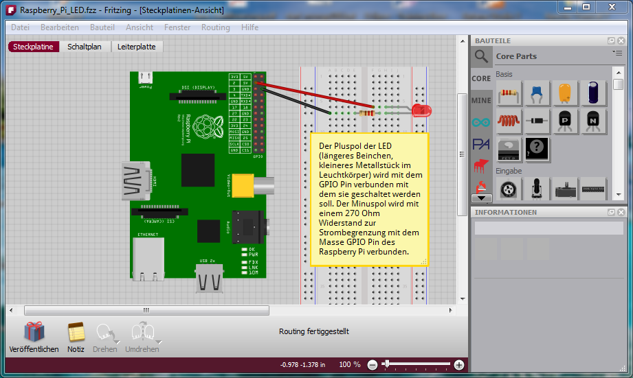
But what sets Eagle’s schematic design tool apart is that you can develop hierarchical designs. Like most EDA/ECAD programs, Eagle comes with schematic and PCB layout design tools. Professional engineers rely on Eagle because it is flexible and it provides large set of high-end circuit design tools. If you are looking for an easy-to-use EDA/ECAD software tool suite that can handle large and complex design tasks, then AutoDesk’s Eagle software is for you. Writing the code, selecting the board, and setting the serial ports works the same as the conventional Arduino IDE. In the Code tab you can write Arduino code and upload it to your board. The circuit you build in the Breadboard view will also be shown as a schematic in the Schematic tab, and as a PCB layout in the PCB tab. Components on the breadboard can be connected with jumper wires, which are created by clicking a terminal and dragging the wire to another terminal. Just drag and drop components from the parts palette window onto the breadboard. The Breadboard view is where you create wiring diagrams.īuilding a wiring diagram in Fritzing is straightforward.

Inside Fritzing, there are five tabs where you can choose the Breadboard, Schematic, PCB, or Code view. You can also create your own parts if you can’t find one online. Fritzing allows you to draw schematics and create PCB layouts, but its most useful feature is it’s abilty to create great looking wiring diagrams.įritzing has a large collection of sensors, capacitors, ICs, displays, and other popular electronics modules.


 0 kommentar(er)
